Construct Logic Circuit For Full Adder
Draw the circuit diagram of full adder with its truth table and working Download 4 bit adder circuit stick and logic diagram Adder logic nand gate implementing
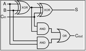
Full Adder Circuit – How it Works
Construct logic circuit for full adder Full adder circuit diagram Adder logic keio sfc
3 bit adder logic circuit design
Multiplexer circuit with logic gatePerforming addition on ibms quantum computers — quantum computing uk Full adderFull adder circuit – how it works.
Adder binary logic input sum output xor theorycircuit boolean diagrams derived following inputs[diagram] logic diagram of bcd adder What is half adder logic circuit?Binary adder/subtractor.

Multiplexer circuit logic gate mux using subtractor full implementation digital inverter symbol bit line multiplexers electronics selector
Logic gatesHalf adder circuit using basic logic gates Adder bit circuit logic carry a1 b1 xor a2 stackexchange hereFull adder circuit – how it works.
Half adder logic diagram and truth table 2 bit full adder a schematicAdder logic Adder binary vidi theory gupta souravAdder vhdl designing 8bit compile simulate waveform verify program.

Digital logic
Computer architecture 2012 fallAdder logic gates theory binary circuits numbers bits calculator equations gupta 8 bit full adder circuit diagramAdder subtractor logic combinational circuits bit binary full using subtraction tutorial add adders sub electronics.
Full adder circuit: theory, truth table & constructionVhdl tutorial – 21: designing an 8-bit, full-adder circuit using vhdl Adder bit circuit half make full logic gates first questions electronics cout second puzzle connecting solved whichHalf adder circuit: theory, truth table & construction.

Full adder em digital logic – acervo lima
Full adder equation74hc83 full adder ic pinout, datasheet, equivalent working, 60% off Adder subtractor bit circuit logic overflow diagram detection designing questions digital15 bcd adder circuit diagram.
.


Binary Adder/Subtractor | Combinational logic circuits | Electronics

Download 4 bit adder circuit stick and logic diagram - Educative Site

Half Adder Circuit Using Basic Logic Gates - Circuit Diagram
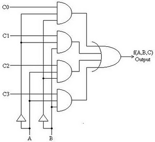
Multiplexer Circuit With Logic Gate - Electronic Circuit

Full Adder Circuit – How it Works

What is half adder logic circuit? - Rankiing Wiki : Facts, Films
GitHub - juliekye/N-Bit-Adder: This Scheme program calculates the sum
![[DIAGRAM] Logic Diagram Of Bcd Adder - MYDIAGRAM.ONLINE](https://i2.wp.com/media.cheggcdn.com/study/ff8/ff85825a-2c2a-4996-82cf-853dc0e1efae/12327-4-19PEI1.png)
[DIAGRAM] Logic Diagram Of Bcd Adder - MYDIAGRAM.ONLINE